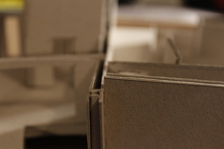
| STEEL COLUMN POSITIONS Although with having no definite dimensions at this early stage of the project, I felt that I could roughly depict where the columns would thread the structure together in plan. This drawing, produced before the construction of my final model (presented within the 'The Pavilion' hyperlink, above and the images below), then dictated the way in which my existing wall thicknesses were proposed upon my final model and how I therefore constructed it. This rough image, drawn originally at 1:50, proposes columns of roughly 2.5m high, in relation to the roofing strategy and thickness that would be placed above such a space. The dimensions of columns that have been portrayed within the drawing (of which are a typical Universal Column form), are of a 20mm flange, with a length of its longest side at 220mm and the central element of 150mm. Although these are not accurate in the slightest in terms of representing the structure tectonically, these portrayed sufficient information within the model making process, seen within the following images. | 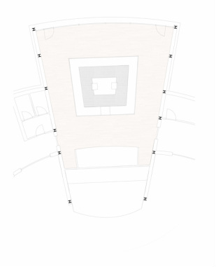
|
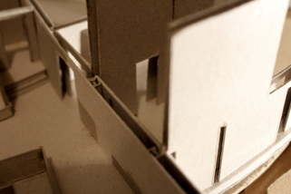
| STEEL BEAM ISSUES Within the design, the columns had been placed as strategically enough to encourage or infer the positioning of the steel beams that would then span the entire space as to support the garden space above. However, the columns are of unparalleled positions in several instances, there fore leading to necessary resolve within my structural strategy. This problem is also evident within the model images, to the left, although in having the central kitchen space as a structural element, may ease some of the tectonic issues of this design. This could be within the inclusion of steel columns, or perhaps a separate grid, within the kitchen space, treating it technically as an individual element within the overall steel frame. There is already existing within this space, a central terminal or element, that is to harness all of the plumbing and electrical services through the bottom of the structure, and can be visible from underneath its raised floor. This took much inspiration from Ludwig Mies Van Der Rohe's Farnsworth House, that also addressed these issues of services in an almost identical way, with due to flood alleviation the structure had been raised (seen within the images). |
| 
|
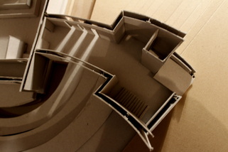
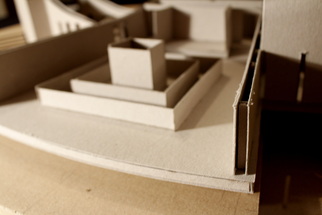
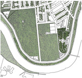
| UNDERNEATH THE FARNSWORTH HOUSE In order to prevent extensive flood damage from the nearby Fox River, Van Der Rohe, whilst designing Edith Farnsworth's 'weekend retreat', had raised the entire structure approximately five feet from the ground, passing all of the structural responsibilities onto the eight stilted steel columns that create the interior space. However, to create this almost floating illusion that had come with the raising of the structure, the services of the home, such as plumbing and electrical connections, all had to pass into the ground. This lead to the solution of creating one single output, seen within the image to the right, as a tube that conceals all of the vital and functional components. This was the solution that I had similarly taken within my own design, although the pavilion that I had designed is supported by a concrete piled foundation which then supports a concrete platform upon which everything is then built up from. This then allowed me to create a concrete pile that of a square shape to create a hollow space in order for services, of the kitchen area specifically, to then travel into the ground. This was a process that I had then repeated within the other areas of the structure, of all the different rooms then having their own piled foundation which then has enough room within its centre to pass below. This can be seen slightly within the images provided of my final model, and of the plan drawn below. These concrete elements had taken large inspiration from the Farnsworth House example (pictured). | 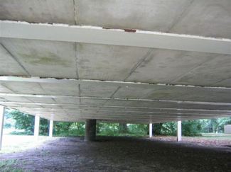
The images above and below are to represent similar ideas in terms of managing structurally, with the services of the structure whilst considering a solution to the steel beam and column issues. 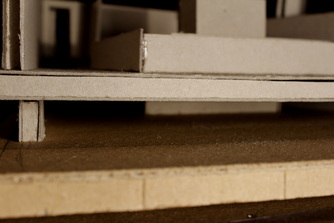
|
 RSS Feed